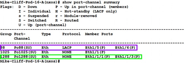

Note: Use command “show mac address-table dynamic vlan 10” on physical switch which represents the same output. The end result is that traffic received from Win Serverin VLAN 10 going to SW is first forwarded to NXOS02, then to NXOS01, then to NXOS04, and finally to SW. This is because other possible paths to the Root Bridge have had their cost raised to 99999. On the next downstream switch, NXOS03, we see that it has chosen Eth1/8, a link to NXOS02, as its Root Port. Use command “show mac address-table dynamic vlan 10” on physical switch which represents the same output. VLAN MAC Address Type age Secure NTFY Ports (T) – True, (F) – False, C – ControlPlane MAC * – primary entry, G – Gateway MAC, (R) – Routed MAC, O – Overlay MACĪge – seconds since last seen,+ – primary entry using vPC Peer-Link, Keep saving your configuration using command “copy run start”.SW’s VLAN 20 traffic to Win Server should follow the path of NXOS03 ->NXOS01 ->NXOS02 ->NXOS04 -> Server 1.

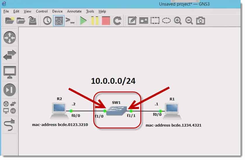
Win Server’sVLAN 10 traffic to SW should follow the path of NXOS03 ->NXOS02 ->NXOS01 ->NXOS04 ->SW.NXOS04 should be the STP Root Bridge for VLAN 20, with NXOS03 being the backup Root Bridge.NXOS01 should be the STP Root Bridge for VLAN 10, with NXOS02 being the backup Root Bridge.All switches should use 32 bits for spanning-tree port path costs.Configure Spanning-Tree Protocol between the switches as follows:.SW’s link to NXOS04 should be in VLAN 10 and use the IP address 10.0.0.2/24.SW’s link to NXOS03 should be in VLAN 20 and use the IP address 20.0.0.2/24.Win Server’slink to NXOS04 should be in VLAN 20 and use the IP address 20.0.0.1/24.Win Server’slink to NXOS03 should be in VLAN 10 and use the IP address 10.0.0.1/24.Create VLANs 10 and 20 on all switches, and assign them as follows:.


 0 kommentar(er)
